Camper build thread

E_T_V
Site Admin
Posts: 439
Joined: Thu Jan 29, 2009 9:38 pm

Camper build thread

Post by E_T_V »

Dans first camper blog

In this blog I'm going to put down my progress (or lack of it), on my maestro campervan.

A brief bit of history:
I bought an old campervan several years ago. It wasn't in wonderful condition but I welded it up and got it an MOT etc and fitted a turbo diesel engine to it to replace the rather old (nearly 200k mile) normally aspirated diesel.

The new engine had a few tribulations, as it went through 2 headgasket changes, but it went well and I tuned it for a LOT more power than it originally came with, ~110bhp by my guestimates.

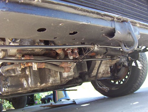
Anyhow a few MOT's later the wheelarches were looking scabby and one of the rear sill sections needed replacing (not suprising since they were originals at 230k miles!). I put on the new sill and one of the arches and then had a poke around underneath and found a couple of tiny holes. These were going to be easier to fix from above so I took the carpet out and had a poke around. To my horror the top of prettymuch every box section was rotten. This was going to be a very difficult repair and would take a long time. It wasn't spotted from underneath so the MOT man wouldn't care, but I wasn't happy with such a structural part being defective and so it was left on the drive whilst I wondered what to do.

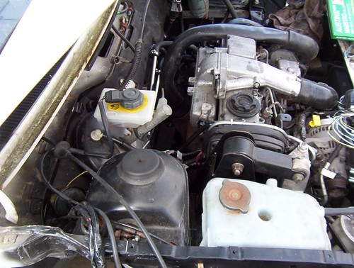
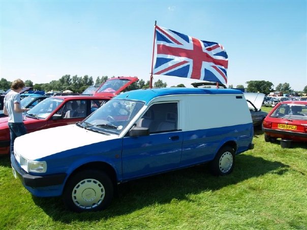
One day whilst browsing e-bay she spotted a ledbury van at a reasonable price on e-bay. It looked ok, but was a petrol engine. However as I've done the diesel conversion already I wasn't too worried. Without even looking at it I clicked the buy-it-now button and arranged to collect it.

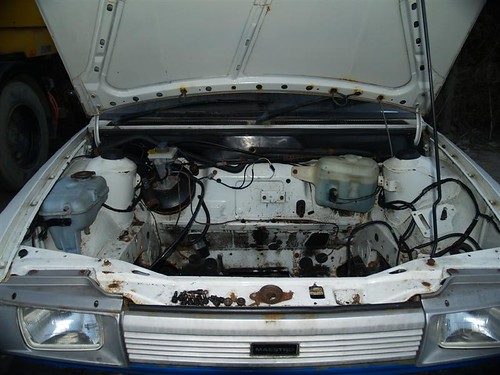
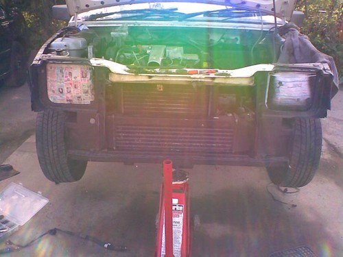
The "new" campervan in the making
Image

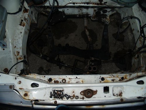
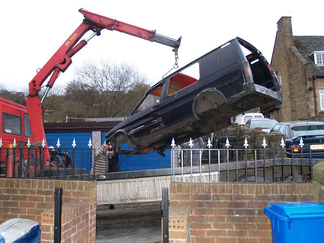
I stripped all the camper specific bits and anything useful out of my campervan and scrapped the shell. I collected the new van and now my mission is to turn my new van into a campervan!

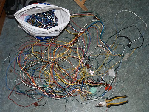
There wasn't a lot left of my van I didn't save!
Image

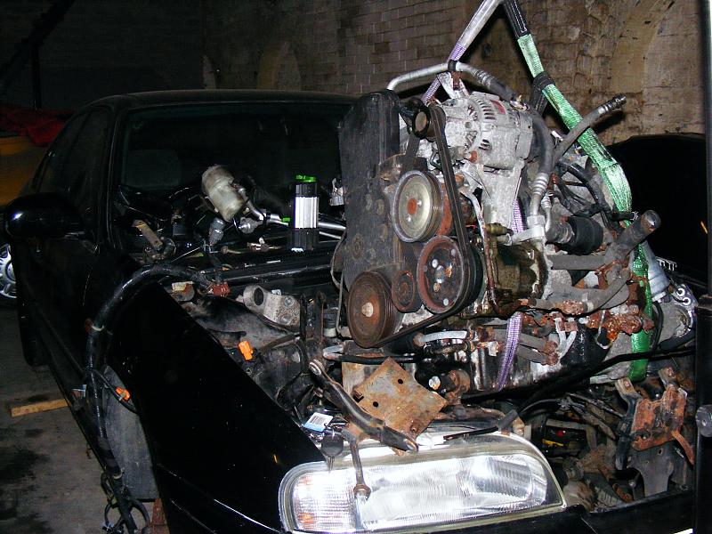
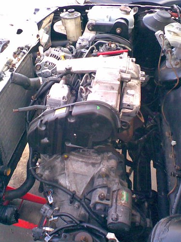
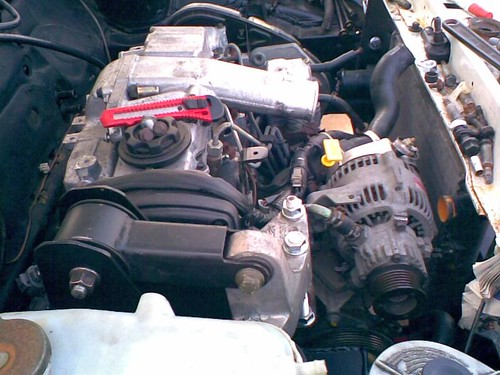
As usually I don't make things easy for myself and it is hopefully going to undergo a colour change and an engine swap too. I'm going to go for diesel again but I'm going for a more modern engine, the rover L series engine (which is the next evolution of the Perkins prima in my old van). I'm making things even more complicated for myself by also wanting to upgrade a few things along the way such as the suspension, the brakes, the wheels, the interior and last but not least the engine!

I'll detail these in future blogs when I get a moment. Hopefully I won't bore you all to tears!

Right thats it from me for now. TTFN.
E_T_V
Site Admin
Posts: 439
Joined: Thu Jan 29, 2009 9:38 pm

2. The start of the end for a 620

Post by E_T_V »

Well I finally pulled my finger out and blagged some space in a friends unit to work.

The transplant begins of a Rover L series diesel into a maestro van.

I realise that the biggest task in this project will be the wiring and pipework, so with this in mind I ordered myself some cable ties which you can use to label stuff with and set about carefully removing the wiring loom from the donor car a rover 600 diesel which I picked up quite cheaply as an engine donor.

Now the wiring on the 600 is rather..... well.... comprehensive is one way of putting it compared to a maestro, and so removing the loom in one piece is a task in itself. Like some maestros and montegos the ECU is inside the vehicle cabin which means that there is a lot of wiring passing through the bulkhead. The 600 also has 2 seperate fuseboxes which will need to be sorted out so that I can integrate the wiring into the maestro. At the moment I'm unsure exactly how the wiring will pan out but I'm getting everything I can out of the donor car in one piece to give me the most options to work with. The most difficult piece will be the alarm and immobiliser unit as the system is quite high tech and installed in of all places the boot!

At the moment I've got all of the engine bay wiring out of the car, and the next stage is to remove the engine and then make a start on removing the wiring from inside the car.

Pics to follow when I remember to take a camera with batteries in!

Right the wiring is out and the engine and gearbox is now on the floor

An action pic

Image
E_T_V
Site Admin
Posts: 439
Joined: Thu Jan 29, 2009 9:38 pm

3. Electrics - electrics - electrics

Post by E_T_V »

Its been a while since I've updated this blog about my camper conversion.

Well I finally got all the wiring out of the 600 that I think I need, and wow is there a lot of it, it takes two of us to load it into my 600's boot. Yee gods, what have I started!

I've spent the past couple of evenings going through the rover wiring diagrams for the 600 so I can chop out a lot of the unused stuff and piggyback the L series ECU onto the Ledbury wiring loom. Time will tell if it will work or not but I'm getting there slowly I think. 10 pages of wiring diagrams done and 10 to go!
E_T_V
Site Admin
Posts: 439
Joined: Thu Jan 29, 2009 9:38 pm

4. The van's engine is out

Post by E_T_V »

Today I took my ledbury van up to a mates unit and then proceeded to remove the engine. This was significantly easier than trying to get the L series out of the donor 600, as it only took a couple of hours to take the old A series out, (compare that with 2 days to remove the L series!).

So progress is being made.

Image

Now I need to clean up all the rust etc in the engine bay and corrosion proof it and then add some soundproofing as the little A series engine doesn't need any. At idle the A series is barely audible with the bonnet closed. Somehow I think I might struggle to achieve that with the L series, but I'll do my best.

Image

If anyone has any good ideas or sources for soundproofing then let me know as I'm struggling so far.

Also another headache is trying to fit a larger turbo to the L series. Whilst the original turbo is good for about 130bhp, I'm greedy and want more. I've found a suitably sized turbo, but sadly its housings are very different to the original one, so making adapters and a new downpipe are on the cards. This is going to be a mamouth project! Ahh well if its performance is anything like what I'm aiming for then it should be a very "interesting" campervan.

Ohh yes I've also managed to source me an uprated clutch spring plate which is essential for my big power plans.

Thats all for now. Photos will hopefully follow!
E_T_V
Site Admin
Posts: 439
Joined: Thu Jan 29, 2009 9:38 pm

5. Wiring wiring wiring again.

Post by E_T_V »

Image


Fitting this engine has to be easy compared to how difficult all this wiring is.

Tonight I spent yet another night trying to do the wiring needed to make the immobiliser work in an alien vehicle.

The picture above is about 1/4 of the wiring loom for the car, after I've disected it and pulled out all the wires I need. Well all the wires I think I need! Only time will tell if I've got the right ones! It doesn't help that I'm colourblind and that there is so many wires in a 600 that some colours are duplicated several times so you have to work out which green and white wire you need!

The next step on the wiring front is the most daunting. Its the ECU wiring. Lets just say there are quite a lot of wires in there to work out what they do!

Another added complication is the fact that I "may" want to try to keep the airconditioning, but that is at an early stage at the moment so plans may change!
E_T_V
Site Admin
Posts: 439
Joined: Thu Jan 29, 2009 9:38 pm

6. The engine is in!

Post by E_T_V »

Today finally the engine is in and suspended from the engine mounts! Hurrah!

Image

Well ok I know it doesn't sound like much but it got me excited. I utilised 2 of the standard engine mounts, (the gearbox one and the rear lower dogbone one). The nearside gearbox mount fits without modification. The rear dogbone mount needs altering a fair bit to fit You have to cut out a fair amount of the aluminium casting on the engine end of the mount, as the sump and the gearbox adapter plate are different to the prima.

Image

Then the offside engine mount was far more of a challenge. The prima uses the rather large water pump to mount from. The L series uses a mount on the front of the engine. So how to mount it? Well I decided that the engine mount in the 600 was well designed and transmitted far less vibration to the car than the prima mount did. So I wanted to use as much of this as possible to keep the comfort in the car. To do this I enlisted the help of a friend who is good with making stuff from scratch for my hairbrained schemes. We started out cutting the prima mount down to form the basis for adapting to make a mount. However in the end he found it easier to make one from scratch using the prima mount as a template for the bolt holes. So the mount arrived and I tried to fit it.

As you can imagine there were some teething problems. I ended up cutting the mount apart, modifying it and then welding it back together.

So I tried to fit it again today and low and behold it fitted virtually perfectly. I suprise myself sometimes. (Its worth bearing in mind that my van is about 30 miles away from my house so I can't just pop out to measure things easily!).

Image

Because of the engihe mount being a lot higher in the maestro than it was in the 600 I need to add a significant spacer between the engine mount bracket and the engine mount. I didn't know the exact size I was going to need to get the engine to sit level etc so I used some threaded bar, lots of nuts and washers to get the spacer effect I need. It'll be replaced with a solid spacer at some point soon but it is strong enough to support the engine for now and is strong enough to allow the engine to be started.

Image

So the engine is in. Next stop the turbo. Hmm I think I'm going to have to rethink my current turbo idea as it just won't fit. Well that isn't true, it will fit but it would mean that either the exhaust would be severely restricted or it would come out of the bonnet. Not really what I'd hoped for. Oh well another minor setback.

I test fitted the intercooler. Actually it might be permenantly fitted now as it is such a tight fit I can't easily get it out again! At least it'll save weight on fixings! Now some more things to think about. The radiator inlet sits exactly where the alternator is. Hmmm not a good start. Also the fan is on the wrong side of the radiator so I'm going to have to find some slim fans to fit between the engine and the radiator.
I might need to find another radiator I think as it looks a little on the small side too. More headaches!

Ok so lets look at the power steering. The reservoir fits nicely using some pre-existing holes in the inner wing. Thats a good start. With some trimming the pump oil feed fits well too! Ahh but with the good comes the bad too. I need to make a PAS oil cooler for it. No big deal really I suppose. Then I need to run some more pipe for the PAS oil return, again no real problem. The hard part will be getting the high pressure pipe sorted. Sadly the fittings on the maestro and the 600 are different so I can't mix and match pipes to make it fit so it looks like I'll have to get someone to make me one. Its one of those jobs where I just don't have the skills or facilities to do it myself, but I guess you can't win them all.

I wonder what tomorrow will bring!
E_T_V
Site Admin
Posts: 439
Joined: Thu Jan 29, 2009 9:38 pm

7. More Van progress

Post by E_T_V »

Well progress is being made at quite a pace now thanks to some help and assistance from a certain forum member.

This weekend the PAS system has been sorted thanks to a new custom PAS pipe and some creative pipe bending to make the PAS cooler. I'll see if I can get some pictures when I'm next up there to show you how it went.

Image

Image

The intercooler pipework is also 99% done (just missing a few hose clips). The L series is a bit strange in that the turbo to intercooler pipework is 51mm and the intercooler to engine pipework is 57mm. So lots of silicone elbows and some lengths of aluminium pipe and its all in. I'm using the intercooler from a Saab which fits neatly and is a pseudo dual pass design which makes the pipework easier. Whether it'll hold up to the boost levels I'm wanting to run I'm not sure, but there is only one way to find out!

Image

The radiator is proving more of a headache. I found a radiator lying around that I thought looked suitable and indeed it is, (far more suitable than the original 1.3 one), however I've found out that it has a hole in it and I'm having trouble sourcing another just like it. I'm sure I can get the original fixed but its another thing to add to the list. The radiator fan was mounted on the front which is space now occupied by the intercooler so that'll have to go on the back of the radiator too. No problem until you realise just how limited the clearance is between the engine and the radiator. I'll have to source a slimline fan from somewhere I think to keep it cool. Another headache was the fact that the radiator outlet was right next to the alternator. The revised choice of radiator has helped moving it further away however now I've got to make pipework that goes up, over and around the alternator! More silicone bits chopped to suit and some joiners made from some pipe I ordered from e-bay, and I think it'll look half decent when it is done. I forgot to buy the jubilee clips so another thing to add to the list! I also somehow need to join the overflow into the headertank. The most obvious point I can see is into the top hose to the radiator as it is the highest point in the system to aid bleeding. So I got some more steel tube, bent it to shape and drilled and welded it into a steel hose joiner in the top hose. I think it looks quite neat but you'll have to judge for yourself.

Image

The wiring is still to do which is going to be one of the biggest challenges. The other one is the turbo which I'm still having a headache with trying to source something the right size that'll give me the performance I'm after and will physically fit!

Lots of things to do still, but at least it looks like the engine belongs there now.
E_T_V
Site Admin
Posts: 439
Joined: Thu Jan 29, 2009 9:38 pm

8. Wiring and plumbing

Post by E_T_V »

Things have been stalled of late due to 2 car shows, a visit to my parents and poor weather.

But this weekend I got a little more done.

I managed to get hold of a maestro turbo radiator for it, and a slimline fan as the space between the radiator and the engine is rather tight.

I've also fitted a Saab intercooler. Whether is withstands the boost pressure or not is another matter but only time will tell.

Most of the pipework is now complete. The PAS is in and the intercooler pipework is almost complete. The cooling system is 90% done with just one more pipe to add and some pipe clips too.

Image

Part of the radiator top hose.

Now the monster job of wiring really commences. The dash is taken out and the two looms put vaguely where I think they belong.

Image

It looks a right mess so trying to make sense of it can take a while.

Fortunatly I have a supervisor who lends a hand... well sometimes

Image

Tony supervising from his reclining chair.

After much sorting and snipping it begins to make a little more sense and I've managed to reduce the amount of wiring needed.


And just to prove it is me doing this work rather than paying some poor sod to do it

Image

Today I started adding the new loom into the original fusebox. There is much more to do but it is getting there slowly. Whether it'll work or not is another matter though... Did I mention I was colourblind?
E_T_V
Site Admin
Posts: 439
Joined: Thu Jan 29, 2009 9:38 pm

9. Fly-by-wire tribulations

Post by E_T_V »

The bigger rover geeks amoung you may have worked out that the rover 600 is a fly-by-wire engine, i.e. the throttle pedal isn't in any way mechanically connected to the engine, i.e. it is all electronically controlled. This means that there is no throttle arm to move which gives me a bit of a headache.

On the 600 the throttle sensor is connected directly to the throttle pedal, something which isn't easy to replicate in the maestro as there is no room. So I came up with an ingenous solution. I used a combination of the original sensor, a throttle cable for a 1.6 maestro, and a few bits and bobs I had lying about.

Image

This is the result I was stuck for places to mount it. Inside the engine bay was a bit vulnerable and difficult to do so I tucked it in a spare bit of space on the centre console. I extended the throw of the original throttle potentiometer as otherwise the throttle was a bit like an on off switch, but now I'm happy with it.

Image

Another problem was the brake switch. On the maestro it just operates the brake lights. On the 600 it also has an effect on the ECU and has 4 contacts rather than the maestro pair. This means I had to use the 600 switch. However there isn't enough room to mount the switch in the original location as it is too deep and fouls the bulkhead. So I had to move it. Obviously moving it meant that there wasn't a contact on the throttle pedal to press the plunger so I had to fabricate a bracket for the switch and a piece of metal to press the plunger when the brake pedal is released.

What do you think?

Image

Image

Most of the wiring is now done, just the dash lights to do I hope. Then I can try and test to see if the wiring is as good as I hope it is!
E_T_V
Site Admin
Posts: 439
Joined: Thu Jan 29, 2009 9:38 pm

10. Turbo troubles

Post by E_T_V »

As people may know I'm a bit of a diesel tuner at heart, and my van is no exception.

I have some aim power figures in mind but I'll keep them under wraps for now. But they are higher than the standard turbo will support.

As some other people might know I'm a cheapskate too and so I didn't fancy splashing out many many hundreds of pounds getting a custom hybrid made. So I found a turbo I thought would be suitable. It was indeed suitable, however the exhaust was totally wrong and pointed at the block. So back to the drawing board. I managed to locate another suitable turbo and with this one I had more luck. It will fit a lot more easily. Note I say will fit more easily, it isn't a direct fit, but it is do-able and here is how I'm doing it

Take 2 flanges that have been cut to fit the original flanges of the manifold and the turbo. And modify slightly with an angle grinder.

Image

Then weld some studs into two of the holes of the triangle flange. Bolt the lower bolts of the bigger flange to the turbo, and grind a little to make them lower than the level of the top flange. I'm using stainless for studs and bolts for obvious reasons!

Image

Image

Then weld the two flanges together after aligning carefully. I've welded both inside and out to ensure a gastight seal, and on the inside I've done a lot of welding so that I can blend the two holes together to enable as smooth a gas flow as possible. This is my first attempt and I'm pretty happy. It'll want a bit more fettling in proper daylight but you get the general idea.

Image
Locked